Measurements Overview

The Measurements module lets you enter values to view your model in 3D and then save the values in a folder for reference and use later. You must select a measure Mode to take measurements.

Measurement window

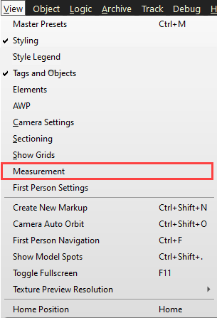
To access the Measurements window, select View > Measurement. The Measurement window opens.

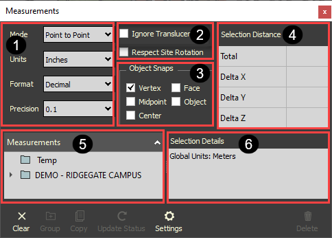
The Measurement window has six sections as shown below:

1

Measurement settings – Measurement settings – You can manage the mode, units, format, and precision of a measurement.

  • Mode - Select between different modes to take your measurements:

    • Point to Point - Basic Point A to Point B measurement.

    • Continuous – Lets you continuously measure along a series of chosen points. Double-click on the last point to end the continuous measurement.

    • Area – Select a series of points that define an enclosed area. Close the area measurement by clicking on Point A. Points picked must be on the same plane.

    • Angle – Lets you pick three points to find an angle.

    • Spot ID – Select a point to show the X, Y, Z coordinates of the point. Spot IDs can be copied to clipboard.

    • Units - Select a unit to be shown when taking a measurement. Units are constrained according to the type of mode selected and will be denoted in italics and cannot be unselected.

    • Format - Select a format to show when taking a measurement. Formats are constrained according to the type of mode that is selected and will be denoted in italics and cannot be unselected.

    • Precision - Select the best precision for your measurement.

2

Measurement options – You can adjust how the measurement tools interact with objects and how measurements are calculated.

  • Ignore Translucent – You can select or unselect the Ignore Translucent objects during measurement mode. When selected, translucent objects in the view window are ignored. This lets you indicate whether translucent objects, such as room, operation, or maintenance volumes are included in the model project. Measurements do not consider translucent objects.

  • Respect Site Rotation - Measurement calculations are defined according to the Site Rotation Values defined on Model stream import.

3

Object Snaps – You can select one or multiple object snaps to define the selection type of taking a measurement. Face and Object are exclusive snaps and cannot be active at the same time.

  • Vertex – Snap to any corner or endpoint.

  • Midpoint – Snap to the middle of an edge.

  • Center – Snap to the center of a face.

  • Face – Snap to any face. The measurement is calculated according to the closest point between the face selected and the other objects involved in the measurement.

  • Object – Snap to any object. The measurement is calculated according to the closest point between the object selected and the other objects involved in the measurement.

  • Freepoint - You can freely capture measurements from any points you select. To use FreePoint measurement, deselect all the Object Snaps options, including the Vertex option which is selected by default.

4 Selection Distance – The total value of the measurement is shown, along with the X, Y, Z deltas when applicable.
5 Measurements – There are two root level groups in the Measurement tree. The Temp group captures all measurements as they are created. The other group shows the Project name, so you can create additional groups and organize project measurements.
6 Selection Details – All the details related to the selected measurement are shown. You can copy and paste in the free-form text section.